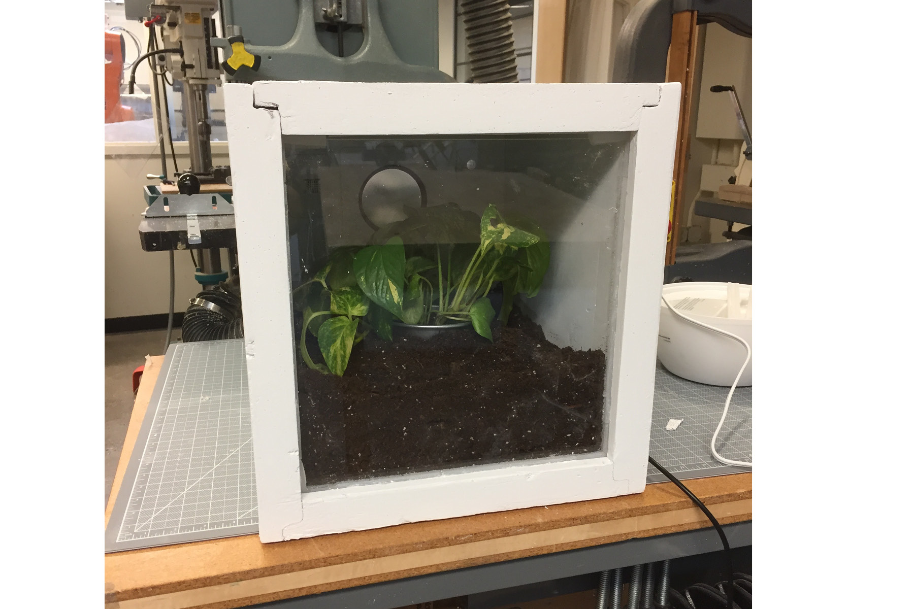
In summary, the terrarium measures temperature and humidity and using a relay device, I can set maximum values to turn on/off the heater/humidifier when that value is met. Inside, I planted a small plant that likes warm, humid conditions.
The design is fairly simple, but there are actually a lot of parts to it. My favorite part of this project was integrating all the bits and pieces to conceal wires and hold everything in place cleanly. Since there were so many different parts to this project (milling, casting, laser cutting, 3d printing AND all the electronics design), I had to keep a close track of my schedule. iPhone siri was my best friend this weekend. "Siri, remind me in 30 minutes to pick up my cast." Everything had a wait time so I had to keep moving between mediums - it was really challenging, but really fun.
Concept
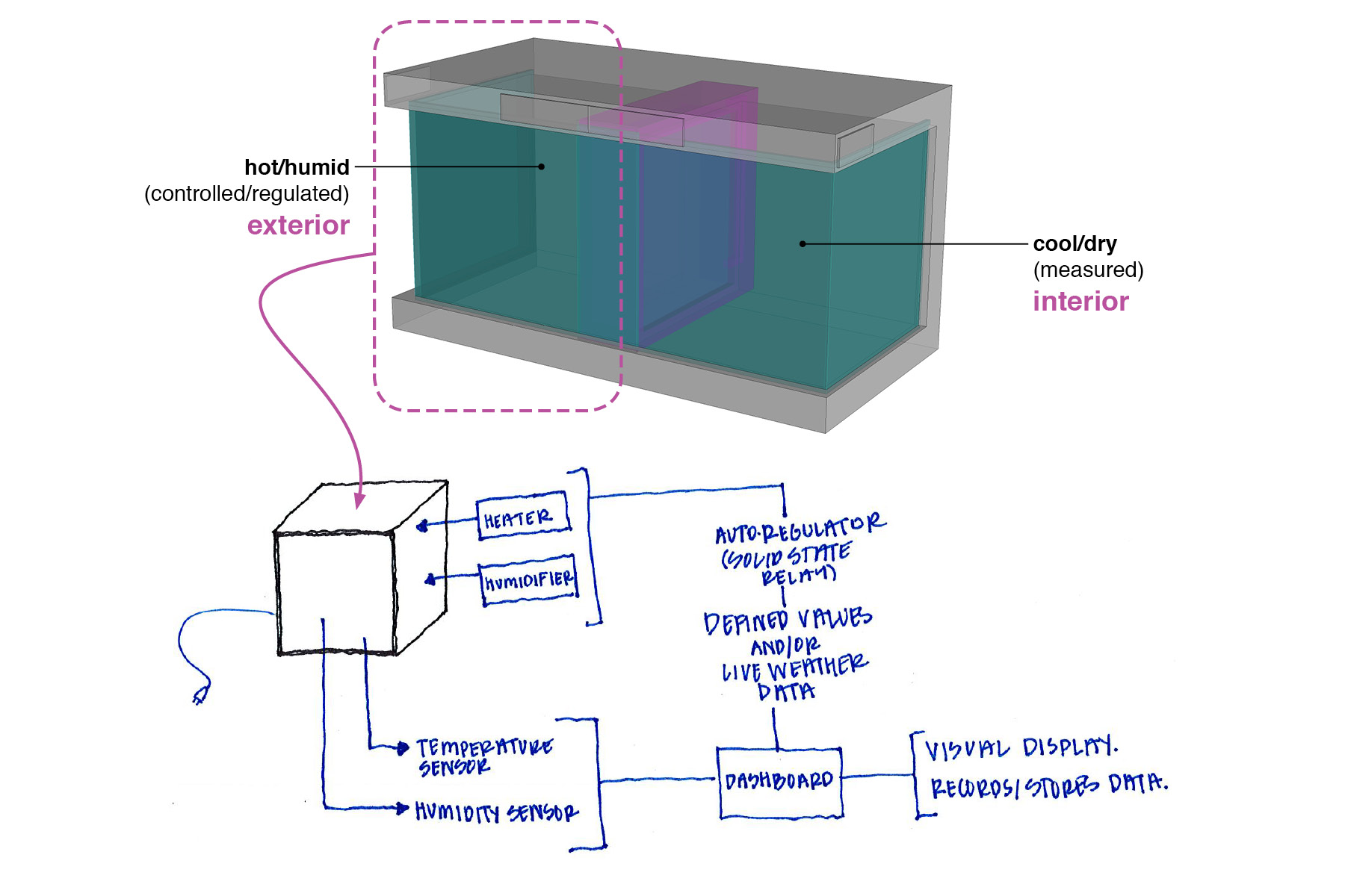
My thermal testing chamber turned into a terrarium at the last minute. The general idea was that there's a hot/humid chamber adjacent to a cool/dry chamber. Between them would be some sort of material assembly that I would desgin as part of my thesis work.
Since I was narrowing the scope of the project down from a two-chamber thermal testing project down to just one, I still wanted it to serve an actual function even in its prototype form. The terrarium has largely the same controls and systems that the thermal testing chambers would have, so I think it's a good study of how it works at a small scale.
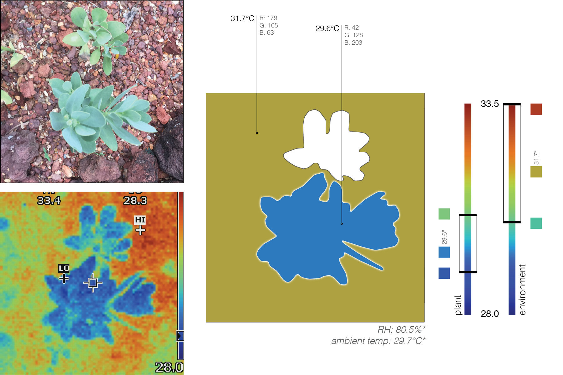
My research atually involves plants experiencing various stressers - particularly as it relates to temperature in humidity. I'm studying a specific metabolic pathway found in tropical plants which is used to survive extreme conditions - I'm looking at this to design building facade systems in tropical climates.
Fabrication
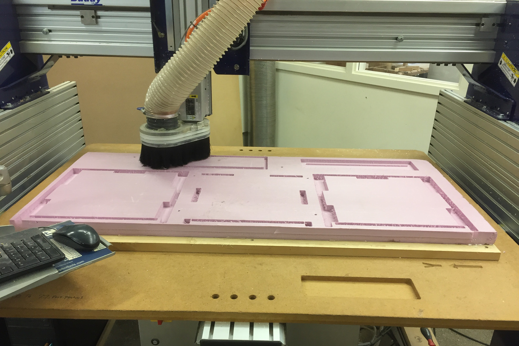
During the "make something big" week, I cut my foam on the onsrud router at n51, but since it's finals, I couldn't reserve any time to use it. I Thanks to Jen and Justin, I was able to learn how to use the shopbot in the architecture shop. The bed is only 24x48" and it doesn't have any suction on the bed, so I had to adhere to the spoil board. This was difficult because the foam was a little warped and the hot glue wouldn't hold it. We had to attach it by screw at locations where we knew the router wouldn't hit the steel screws. The actual milling time took about 20 minutes per sheet. I set up the files using mastercam. I cut the foam at a spindle speed of 18000 rpm, and I found that the higher speed made for a smoother cut than the lower speed.
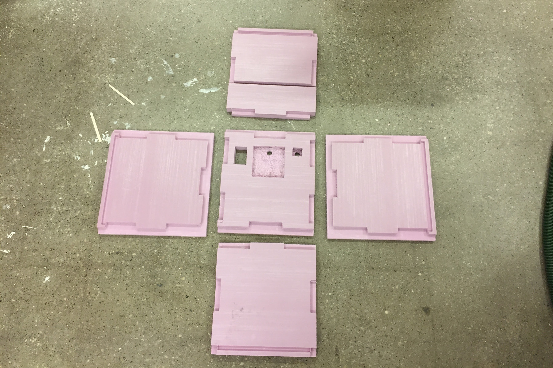
Here are the five sides of the box. (You may notice that the inner cuts on the center piece are a little rough - I somehow left these out of the toolpaths, so I had to cut them "by hand" on the drill press). The pieces slid right together and held in place mostly by friction. Since I was going to paint the box, I also screwed the corners together to make sure the joints would stay tight. When I end up building the actual thermal testing chambers, I'll have to reevaluate this, since it would create a bit of a thermal bridge.
The inner space of the box is 1 cubic foot, so the actual dimensions of the pieces were about 13 inches.
The 1.5" foam came from home depot and cost $24. I had intended to use 2" but they were sold out. 1.5" worked well.
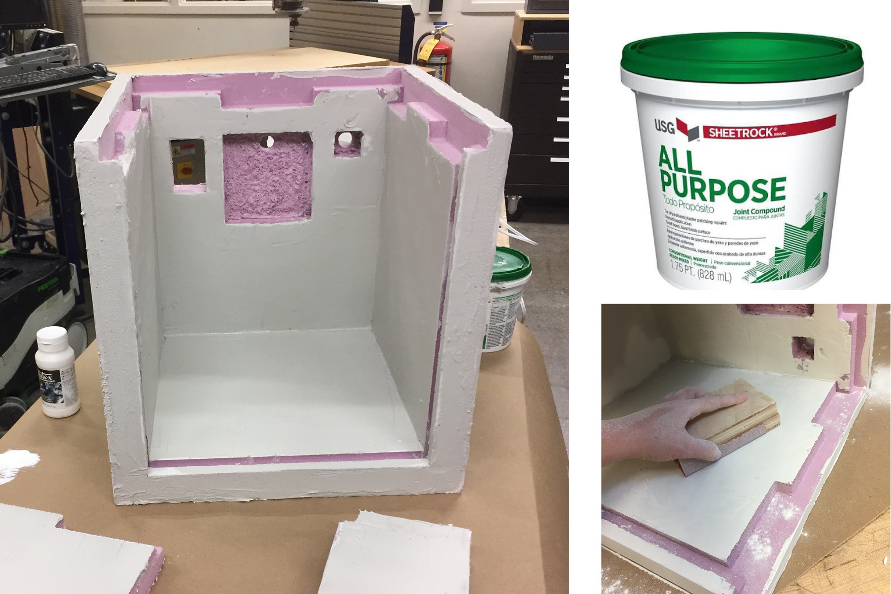
I used pre-mixed joint compound ($4) from home depot on the foam. It's plaster-based, dries quickly (a few hours) and adheres well to the foam - I applied it with a spackling tool. It sanded beautifully but made a MESS! Do not sand it in a wood shop, as the dust gets everywhere and damages the tools. I've used gesso in the past, but I wanted something thicker that would give the box a little more structure and hide the joints. Gesso also takes several layers to get any sort of workable quality.
The final coat on the box is white latex paint that I found in the shop. It was old and required a lot of stirring.
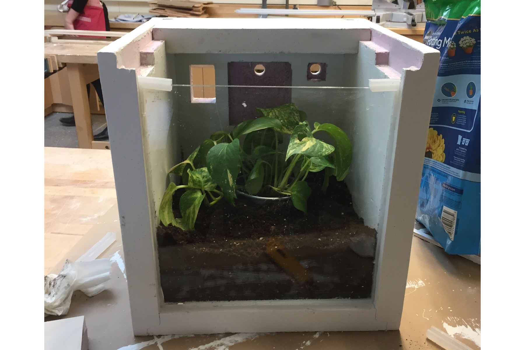
I used 3/16" acrylic (purchased at Altec plastics in South Boston. The whole sheet cost $20, but I used only about a third of it). I cut it on the laser cutter. Putting the plastic sheet into the gaskets was tough, and took a bit of effort.
Once the paint had (mostly) dried and the acrylic sheet was in, I dumped in the dirt and potted my nice plant. This all came together really quickly, and I wasn't able to finish it as nicely as I had hoped. Ideally, I'd like to sand the paint and add another coat.
Gaskets
My favorite part of the project was designing and integrating all these bits and pieces. It's fun to think about the big picture, but with all these moving parts, it's important to consider how they all come together.
The first step was gaskets, and this carries over a bit from the molding and casting week. I wanted to add an airtightness component to the box. The acrylic can slide pretty easily into the slots routed out for it, but with the sharp corners and the softness of the foam, it was susceptible to holes and punctures. I wanted something to exist between these materials, so I designed and created silicon gaskets.
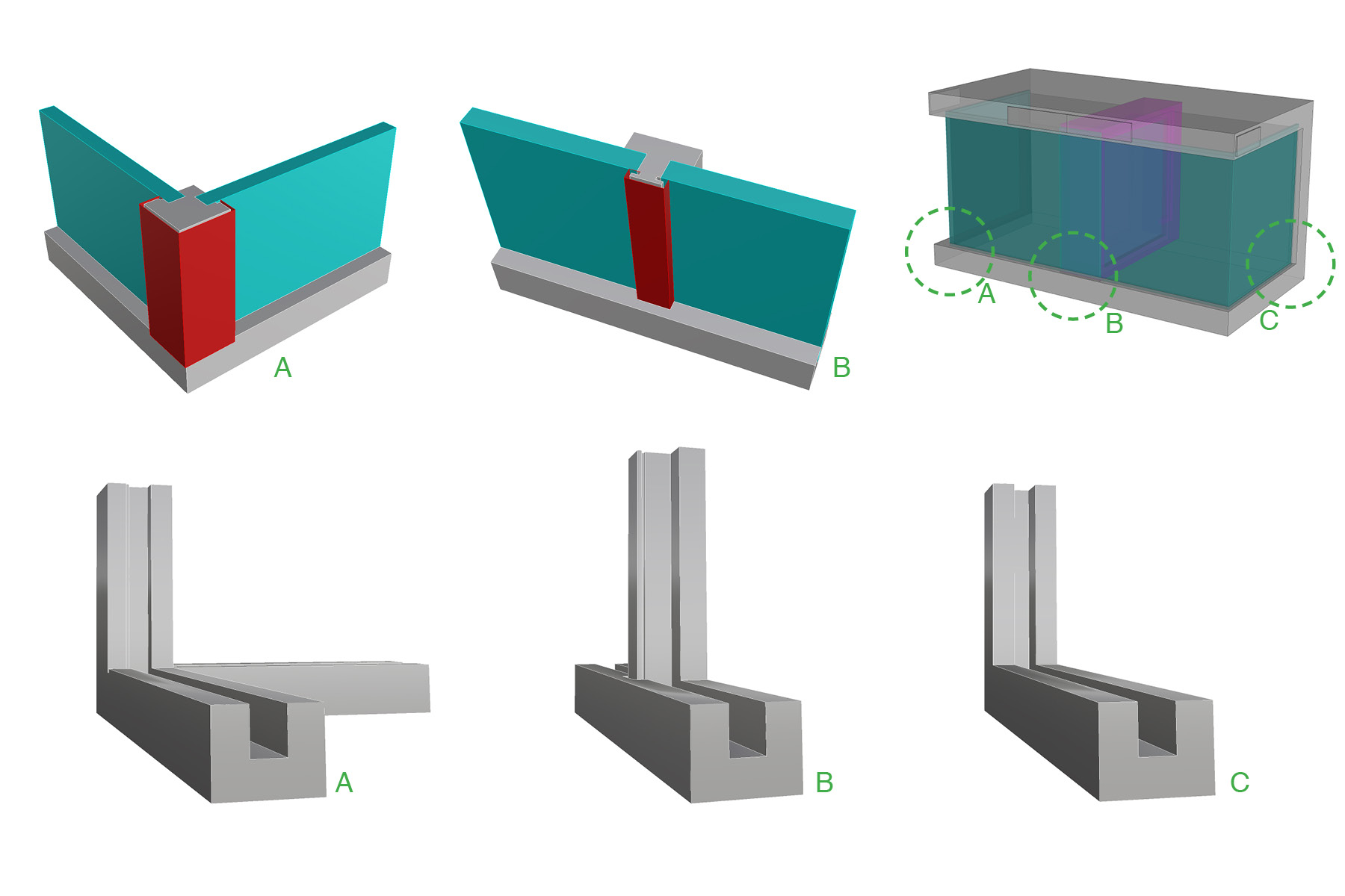
The original box design was much more complicated, and had several different conditions where the acrylic met acrylic (A and B) or when it met the corner (C). I ended up only needing the C condition shown above.
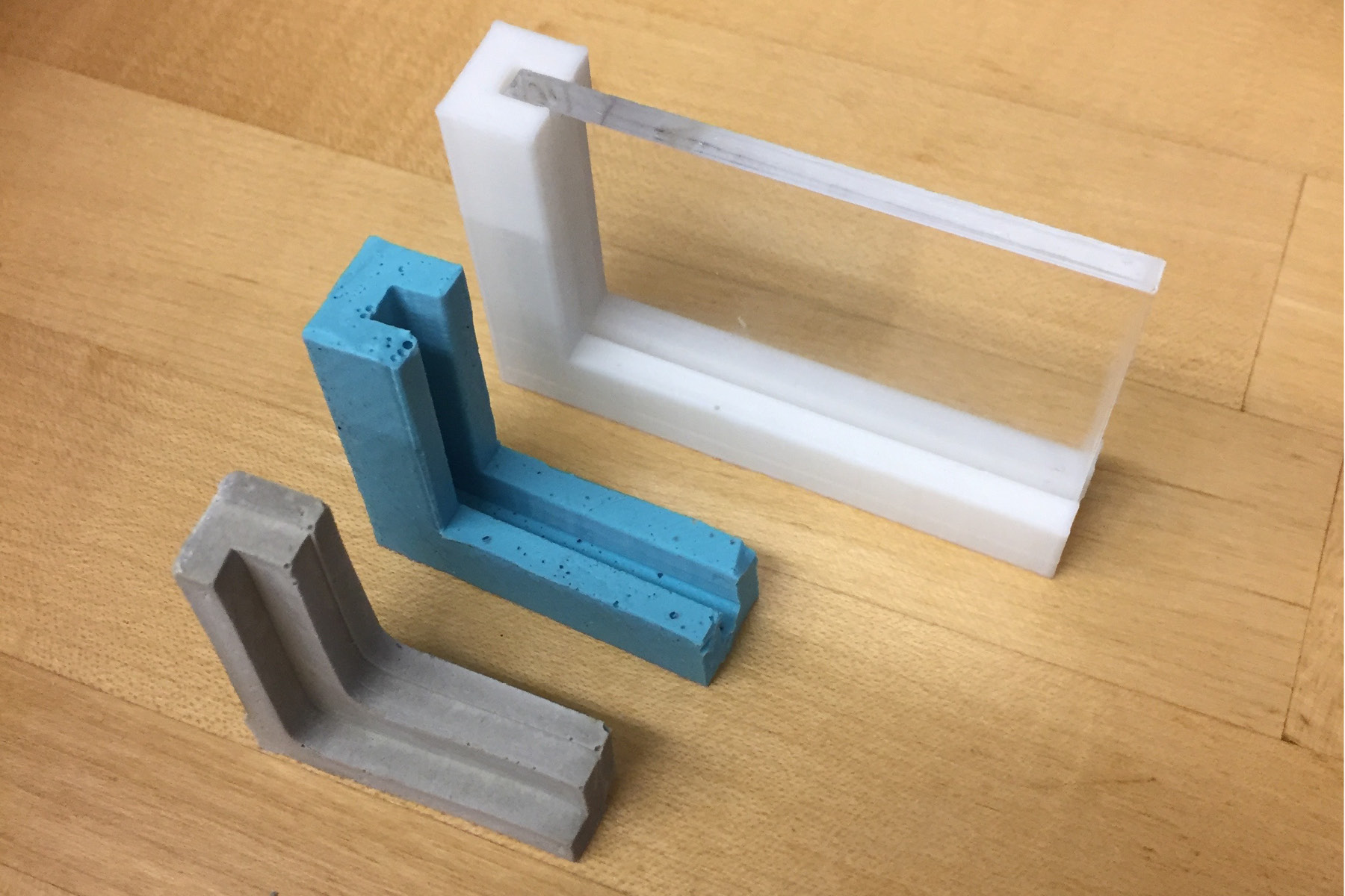
I attempted to make a mold in the molding and casting week, but was largely unsuccessful. The 3d-printed piece (with the laser cut acrylic inset) at the top of the image was what I was hoping for the hydrostone piece to look like. Alas...
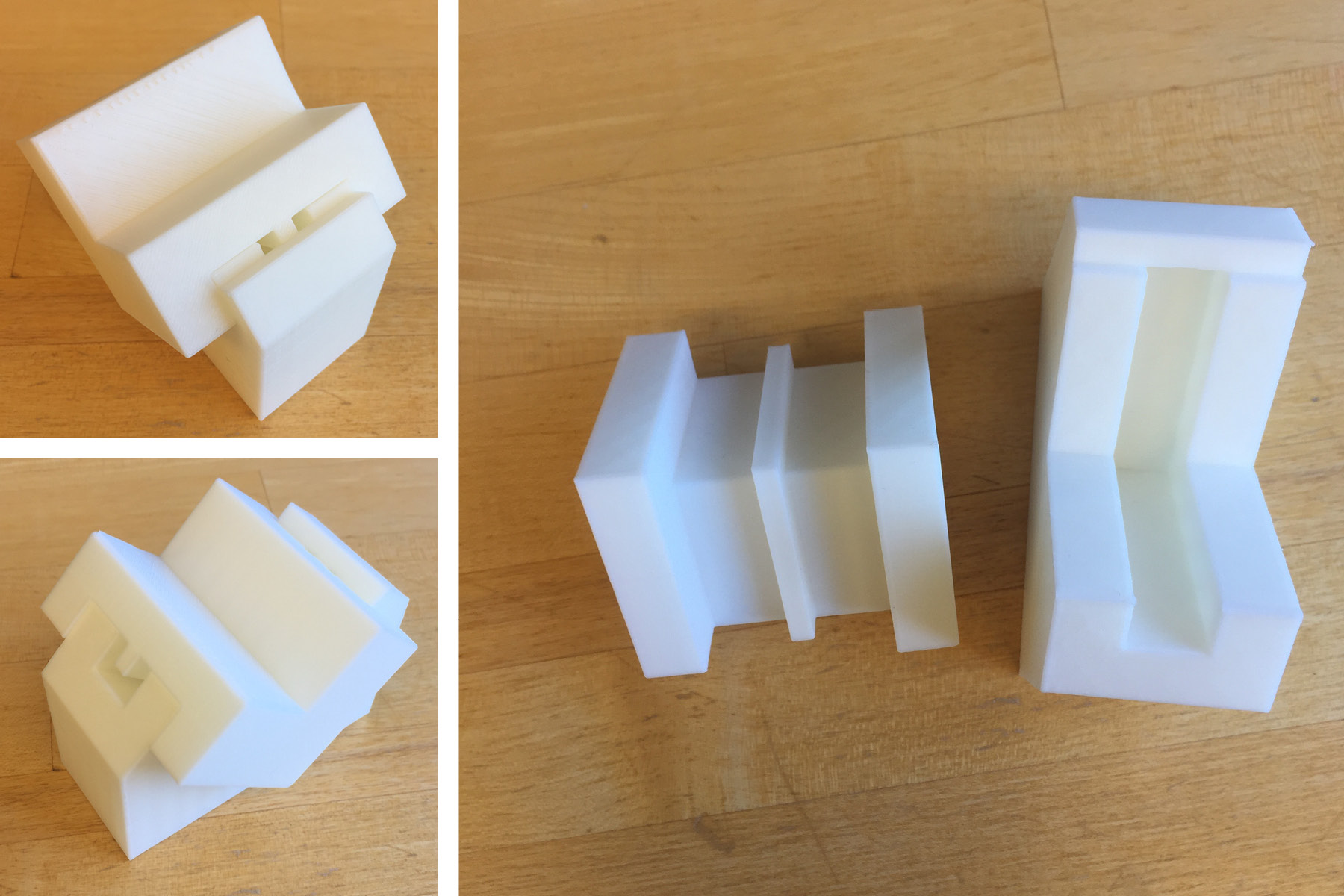
So a few weeks later, I created a new mold on the 3d printer. This file took almost a full day to print, but it was perfect for what I needed it for. The only problem was it was a little too tight, so I had to use a hammer to separate the two pieces.
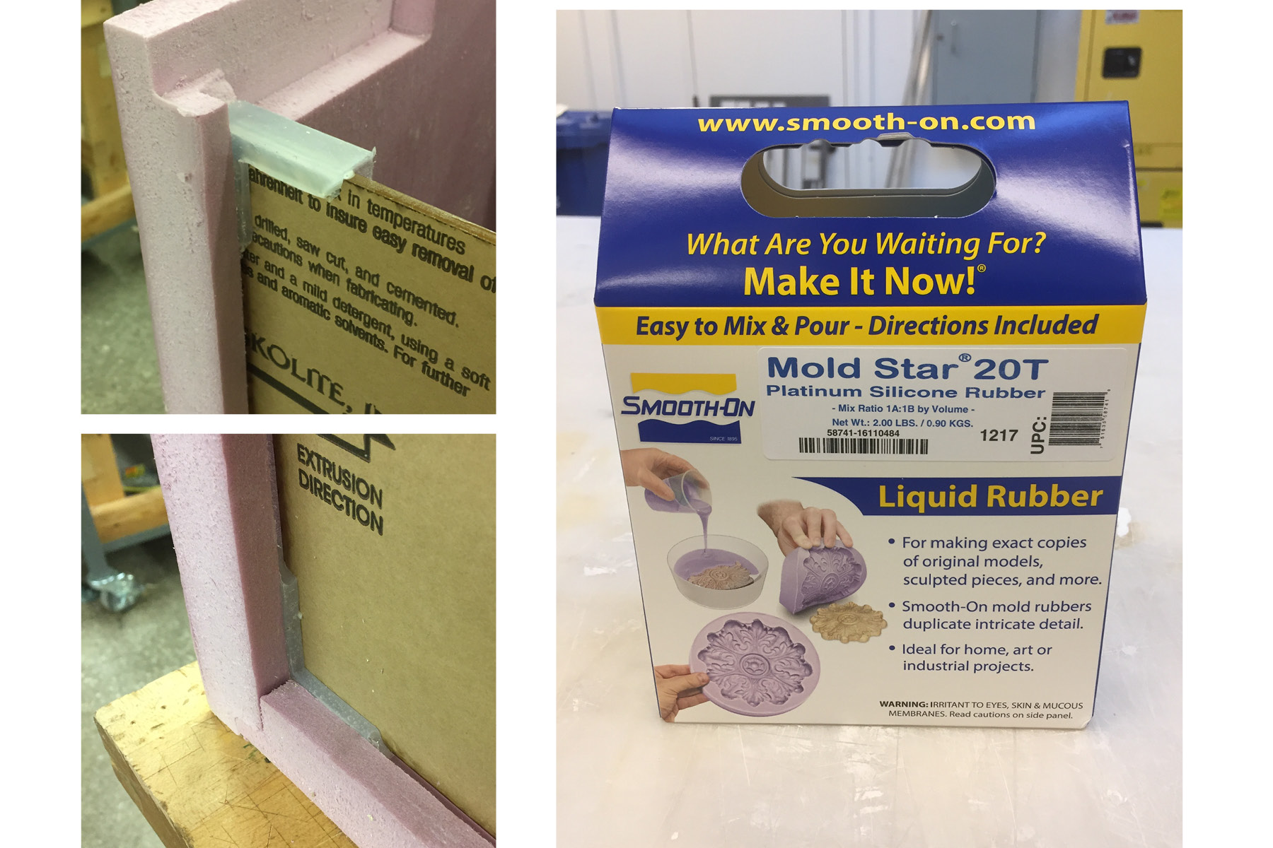
I used Smooth-On Mold Star 20T that I purchased from Reynolds Advanced Materials in Boston. It cost $30 - I'll also note that it has a 6 month shelf life. I bought an extra package, just incase I needed more, so I'll need to keep that in mind. It was easy to work with and worked a lot like the oomoo. I found that it got dirty really easily though.
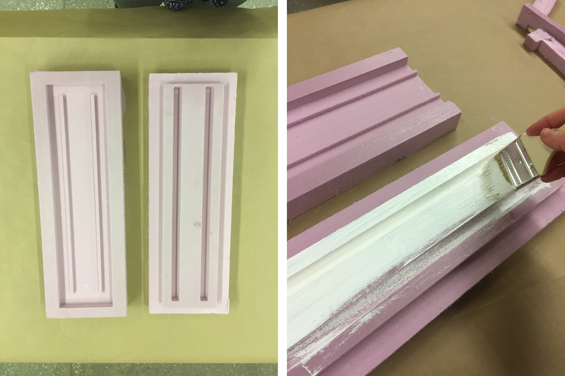
While I was milling the box, I also milled a mold for the straight part of the gaskets. I used two coats of gesso to smooth this out. The silicon picked up a lot of the texture, but it was OK for my application, since it was hidden in the foam slot. The mold was surpisingly durable and I used it for three casts, but it probably wouldn't hold on much longer. It was also too long (14") and I needed to allow for more air holes. I had a number of large airbubbles that had no way to escape, no matter how much I vibrated the mold.
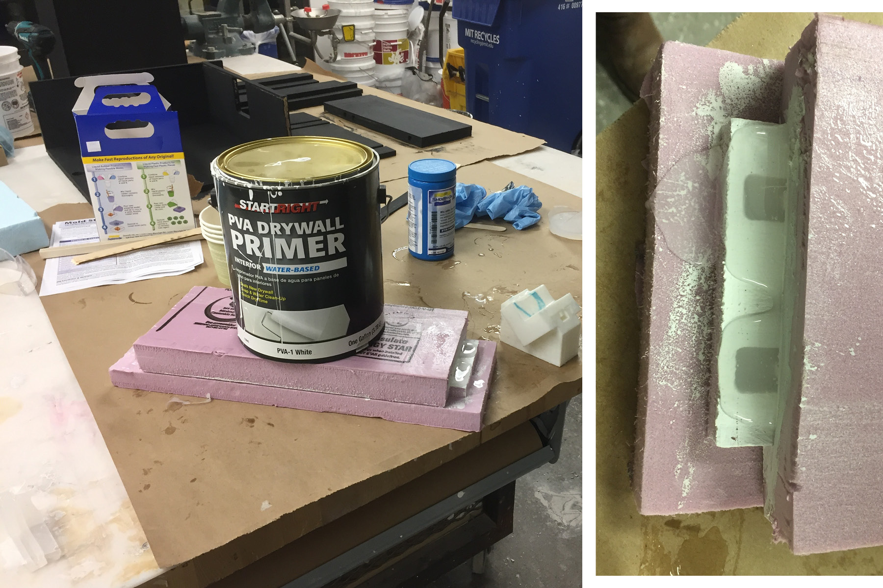
I set a large can of paint on the mold while it was curing to keep any space from forming between the two pieces. The image on the right shows the silicon oozing out of the mold.
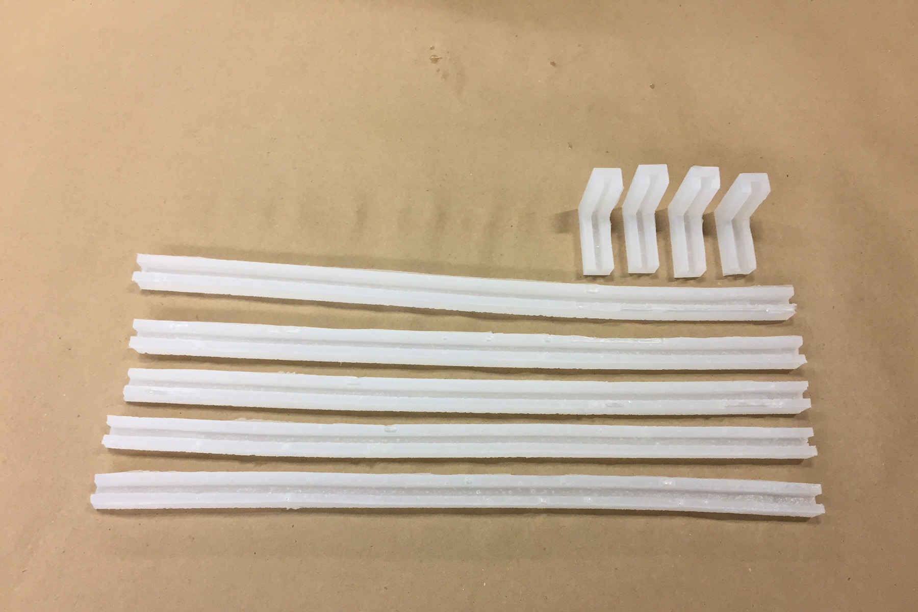
And here are all the gaskets together. I love them!
Bits and Pieces
Since I had a number of penetrations in my box, I wanted it to be really clean, especially since foam can look so rough at the edges. I was able to squeeze in quite a bit of time with the 3d Wox 3d printer to build my pieces. If I was mass producing this box, these would be great candidates for molding and casting.
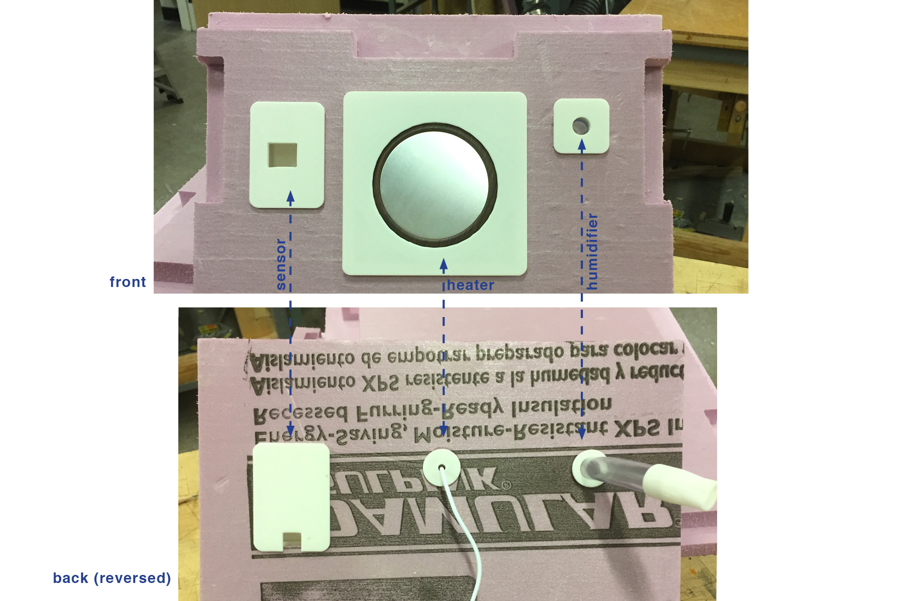
The image above shows the front and back of the box. The back image is reversed to show how each piece matches up at the back. I ended up not being able to use the plate over the back of the sensor - I designed the plate before I designed the board... who knew it would need to be plugged into so many things???
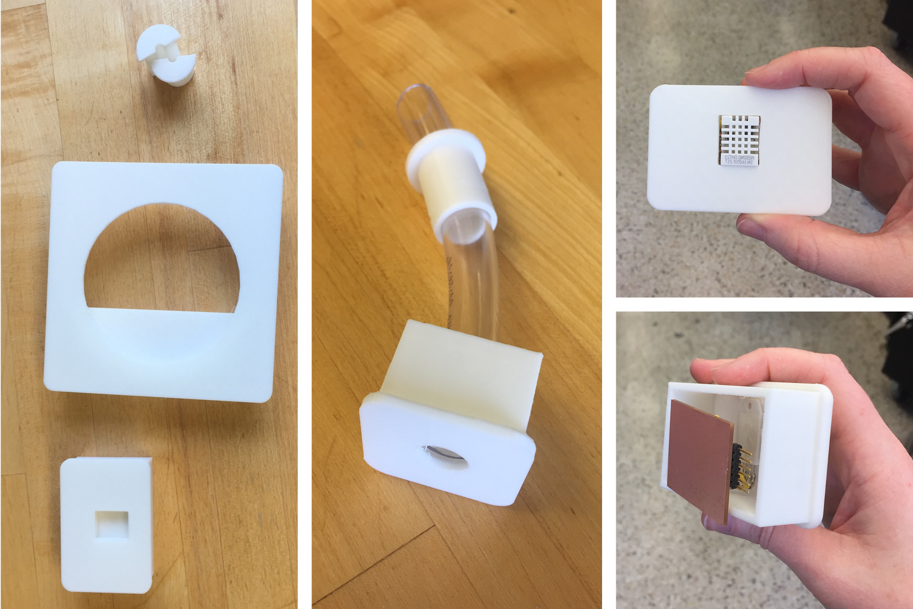
Here's a closeup of some of the parts. The center image shows the 1/2" vinyl tubing ($4 from home depot) that I used for the humidifier connection.
The image on the far right shows how the sensor integrates into the box. This is my absolute favorite part of this project.
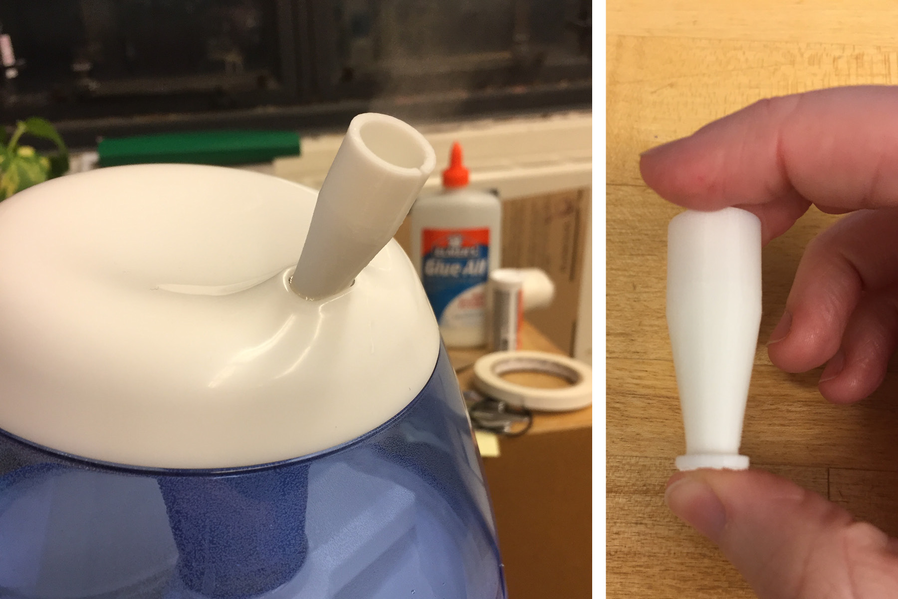
Since the humidifier had a different size opening then the vinyl tubing, I designed a small piece to accomodate this difference - it worked really well. It took several iterations to figure out the correct sizes, so fortunately each print only took about 28 minutes.
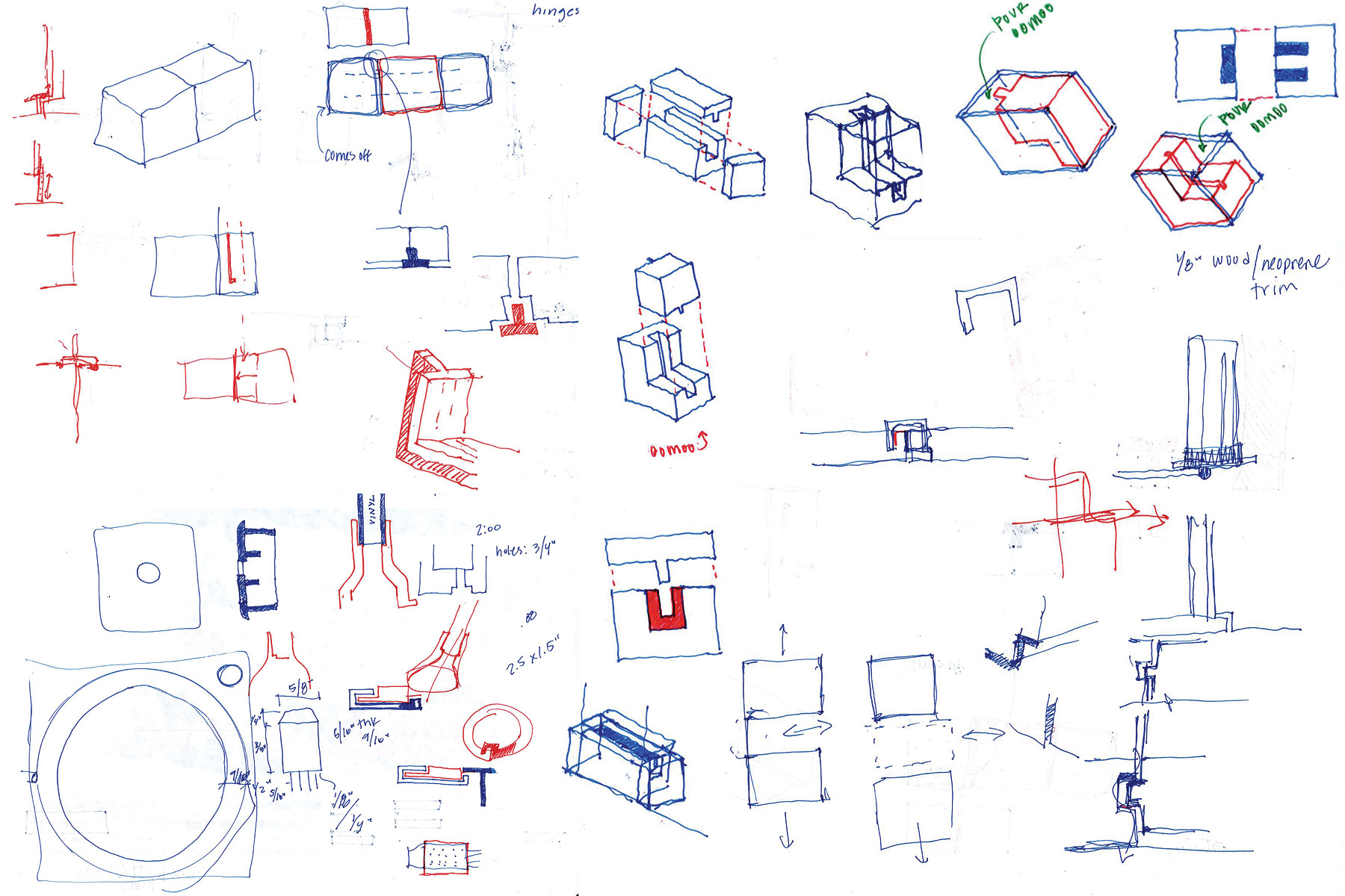
While the actual modeling happened in Rhino, I had to figure out most of the various pieces by hand. The image above is a combination of sketch on 5 different pages. While everything is becoming much more digital, I belive that the digital realm must always have a strong footing in the analog world. Sketching is essential.
Electronics
Disclaimer: I have absolutely zero electronics experience, so please be wary of my process. I couldn't have gotten through this part of the class without Calvin, Hunmin, and Yasaman - the architecture shop TA's.
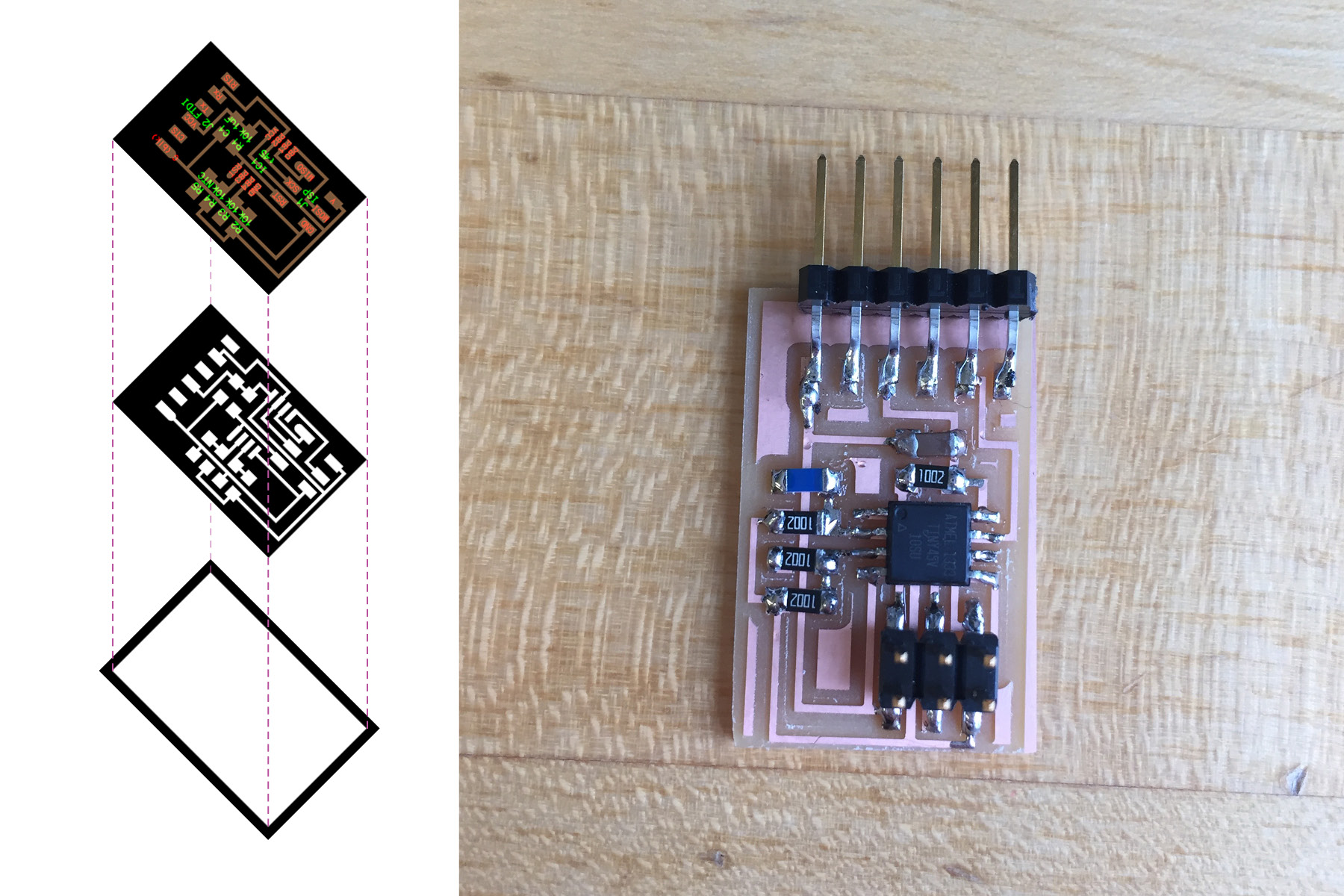
Early in the semester, I built Neil's temperature sensing board. This was well before the input design week and with the help of Justin, I was able to get it programmed, but I didn't find the temperature to be particularly accurate. I didn't do any design with this board, but it was a good first step in the process. I'd recommend starting with something like this before beginning the process.
For the "Input Devices" week, I bought a DHT-22 Temperature chip from Adafruit , as I found that a number of past students have successfully used this same device. I used Neil's Arduino board with the addition of a 10K resonator between the sensor data pin and power (as recommended by the data sheet) and a capacitor (but it turns out that I didn't really need the capacitor after all).
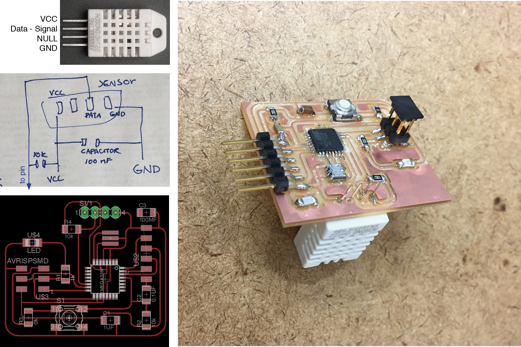
For the "Input Devices" week, I bought a DHT-22 Temperature chip from Adafruit, https://www.adafruit.com/product/385, as I found that a number of past students have successfully used this same device. I used Neil's Arduino board with the addition of a 10K resonator between the sensor data pin and power (as recommended by the data sheet) and a capacitor (but it turns out that I didn't really need the capacitor after all).
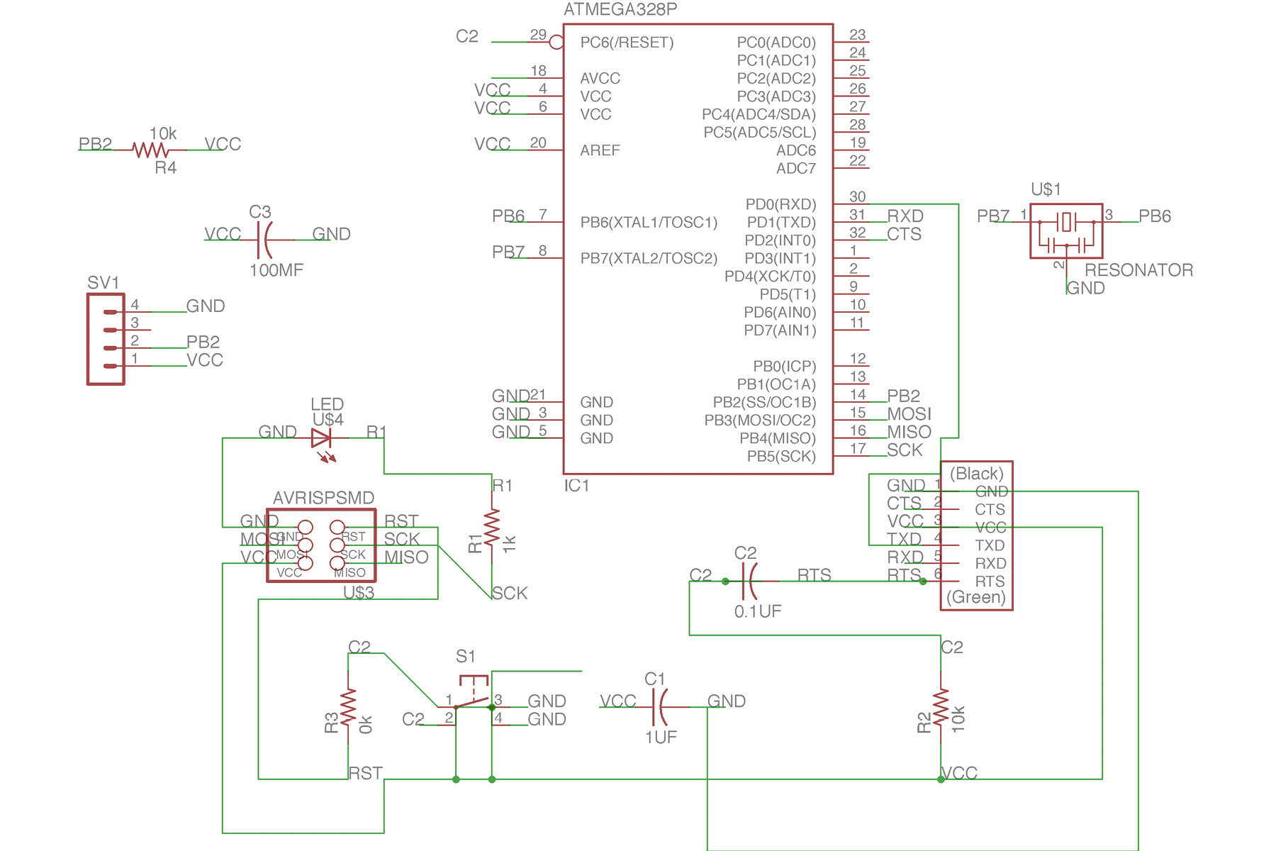
I design the board in Eagle and had a hard time sorting out the traces. I ended up using "autotrace" to figure out the routes, then redrawing them myself. This board uses the Atmega 328P, which was a total bitch to solder. The above image is the schematic I created in Eagle.
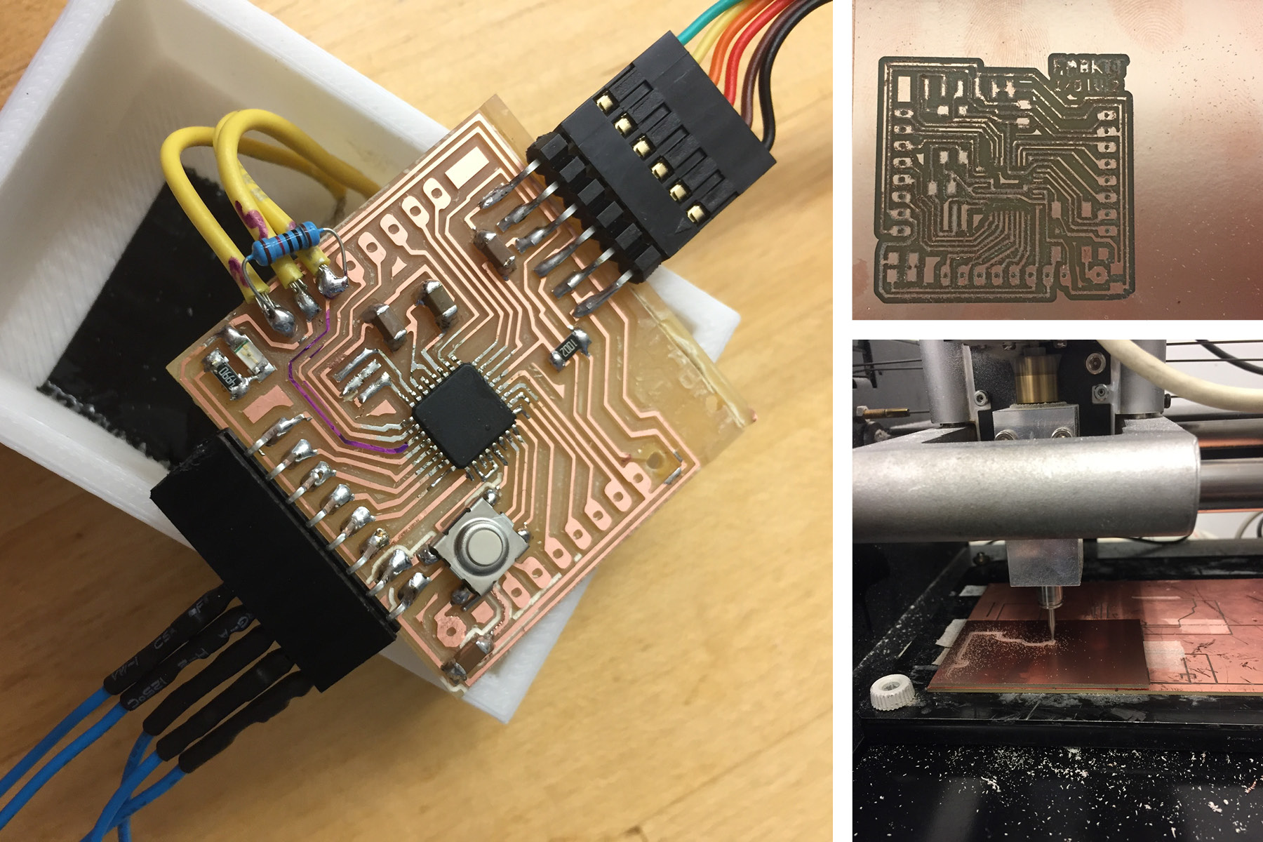
The final board that I made (and used in the final project) was the fabkit board (with an added resonator). Given the scope of the project and the amount of time I had left, this was really my only option.
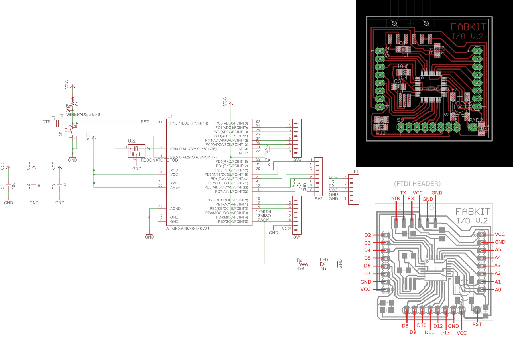
The fabkit board is an arduino-friendly board with multiple empty pins. Since I wasn't entirely sure how my electronics would be working, I appreciated the flexibility that this board provided. The above images come from the author of the fabkit tutorial, they are not my images.
I had quite a bit of struggles with the board - first of all, I wasn't able to mill the holes, which I didn't think would be a problem, but then I ended up using a lot of the empty pins, so I had to work out some solder magic.
Using the directions from the fabkit site, I couldn't get the bootloader to work. In fact, I couldn't even get the library to load. No one in my section could figure this out, so the problem was never resolved. I was finally able to burn bootloader after I installed a 16 mhz resonator. 20 did not work, which is what I used on my previous board. Make sure you have your speed set right. See the image after the code below. (Burning the bootloader means that you can work with your board without using your programmer. This alleviates a bit of wiring connections and just generally simplifies things. It's still possible to program your board without burning the bootloader, though).
Using the DHT-22 arduino library file, I was able to get the sensor to read temperature and humidity. The only thing I had to change was the pin number (and since arduino uses different pin names then the Atmega data sheet, I had to look up the conversion process. This is outlined in the "input devices" week). Here's what the code looked like for that test:
#include

#define DHTPIN 2     // what digital pin we're connected to

// Uncomment whatever type you're using!
//#define DHTTYPE DHT11   // DHT 11
#define DHTTYPE DHT22   // DHT 22  (AM2302), AM2321
//#define DHTTYPE DHT21   // DHT 21 (AM2301)

// Connect pin 1 (on the left) of the sensor to +5V
// NOTE: If using a board with 3.3V logic like an Arduino Due connect pin 1
// to 3.3V instead of 5V!
// Connect pin 2 of the sensor to whatever your DHTPIN is
// Connect pin 4 (on the right) of the sensor to GROUND
// Connect a 10K resistor from pin 2 (data) to pin 1 (power) of the sensor

// Initialize DHT sensor.
// Note that older versions of this library took an optional third parameter to
// tweak the timings for faster processors.  This parameter is no longer needed
// as the current DHT reading algorithm adjusts itself to work on faster procs.
DHT dht(DHTPIN, DHTTYPE);

void setup() {
  Serial.begin(9600);
  Serial.println("DHTxx test!");

  dht.begin();
}

void loop() {
  // Wait a few seconds between measurements.
  delay(2000);

  // Reading temperature or humidity takes about 250 milliseconds!
  // Sensor readings may also be up to 2 seconds 'old' (its a very slow sensor)
  float h = dht.readHumidity();
  // Read temperature as Celsius (the default)
  float t = dht.readTemperature();
  // Read temperature as Fahrenheit (isFahrenheit = true)
  float f = dht.readTemperature(true);

  // Check if any reads failed and exit early (to try again).
  if (isnan(h) || isnan(t) || isnan(f)) {
    Serial.println("Failed to read from DHT sensor!");
    return;
  }

  // Compute heat index in Fahrenheit (the default)
  float hif = dht.computeHeatIndex(f, h);
  // Compute heat index in Celsius (isFahreheit = false)
  float hic = dht.computeHeatIndex(t, h, false);

  Serial.print("Humidity: ");
  Serial.print(h);
  Serial.print(" %\t");
  Serial.print("Temperature: ");
  Serial.print(t);
  Serial.print(" *C ");
  Serial.print(f);
  Serial.print(" *F\t");
  Serial.print("Heat index: ");
  Serial.print(hic);
  Serial.print(" *C ");
  Serial.print(hif);
  Serial.println(" *F");
So once I ran that code... I didn't get any errors... but where did the data go? Do I need to build an interface to read it? Fortunately arduino has a built in reader, just go to Tools>Serial Monitor. Good stuff. Here's what that looked like:
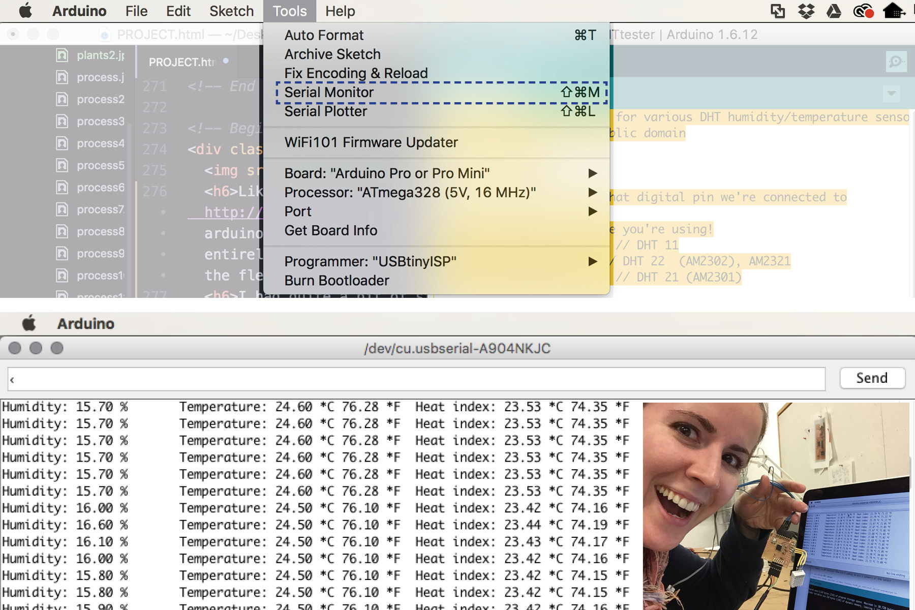
Temperature and Humidity readings. I literally cried with happiness when I got this working. What a cool feeling. Thank goodness for Hunmin magic. Now onto the output.
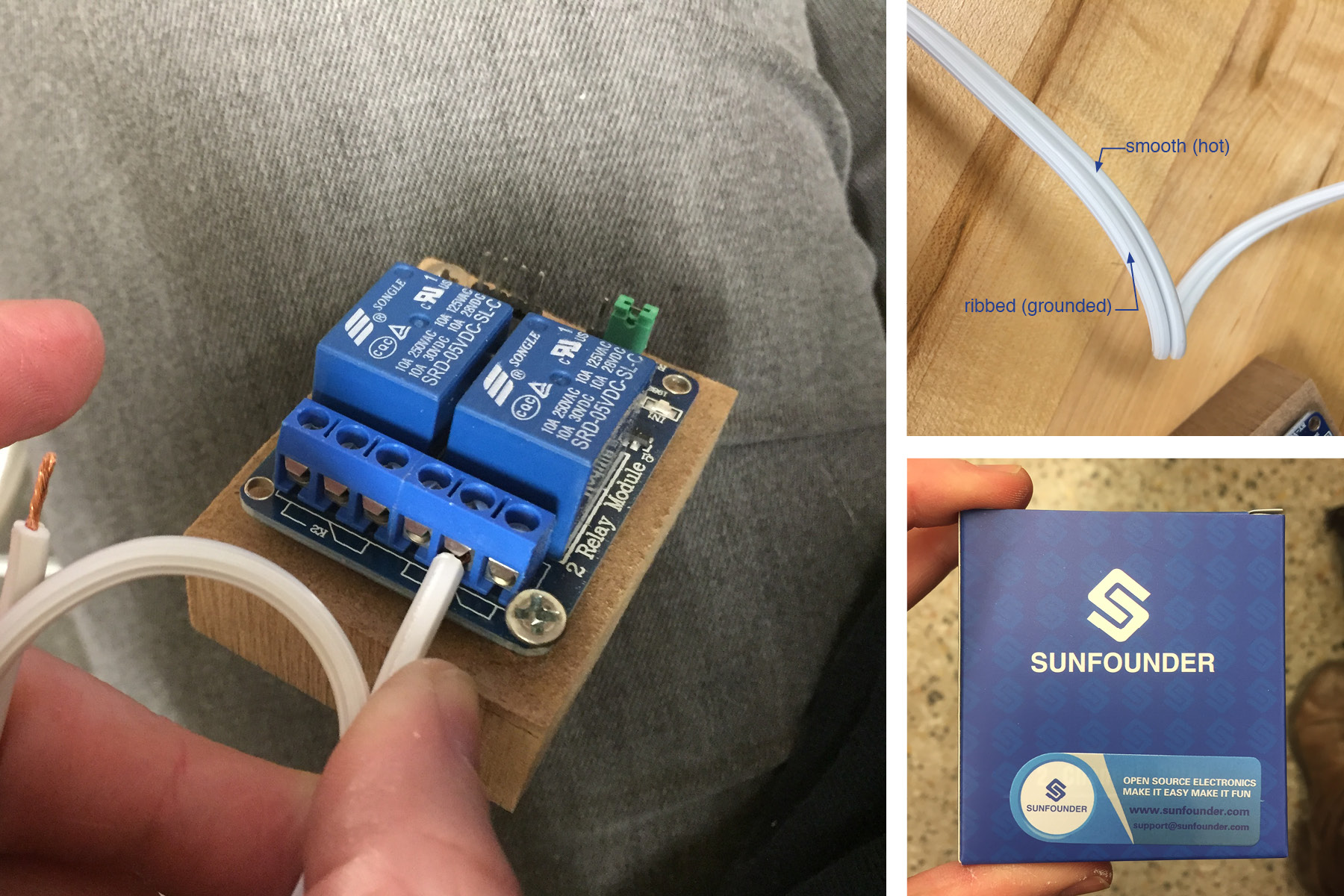
With the recommendation of my colleagues, I bought the "SunFounder 2 Channel DC 5V Relay Module with Optocoupler Low Level Trigger Expansion Board for Arduino UNO R3 MEGA 2560 1280 DSP ARM PIC AVR STM32 Raspberry Pi" to go with my fabkit board.
Using this device was somewhat intimidating since I'm actually rerouting the power supply to various devices. The first step is to cut only ONE of the two wires, stripping it, and stuffing it into the box. I never knew that power cords had two different types of wires - one is grooved/striped/ribbed and the other is smooth. The grooved wire is grounded (neutral) while the smooth wire is ungrounded (hot). The smooth (hot) wire connects to the relay, so cut that one.
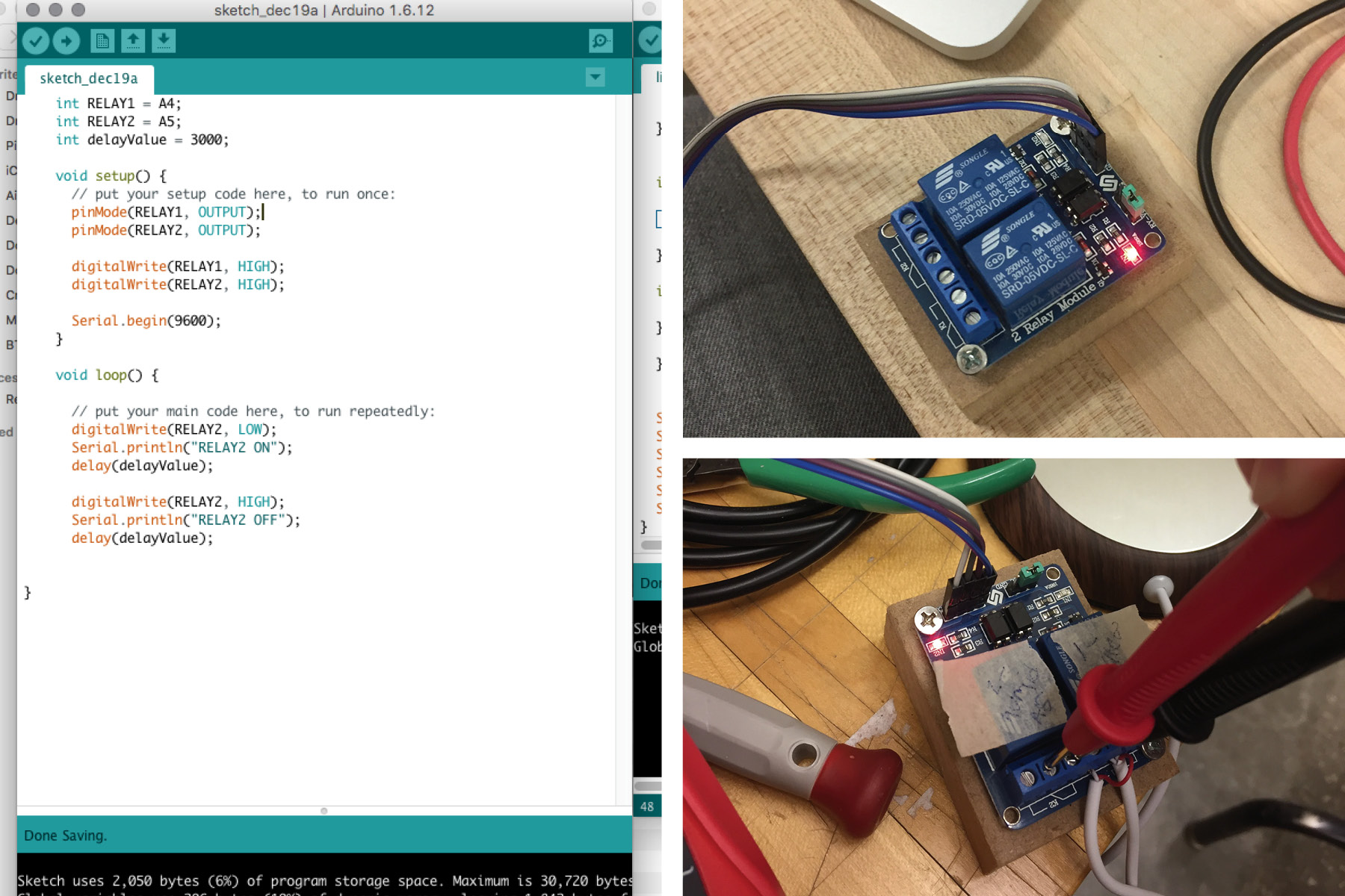
I used some code that I found online to test the relay. It turns it on and off - you can tell it's working if you hear a click and the red light flashes. Very cool. Before plugging it into the power source, we made sure that the pins were active and the code was working, using a micrometer.
I should add that there is a bit of a shock risk with this thing, and Hunmin recommended that I put something over the back of the board since the pins go through. Also when you're stuffing the wires in, make sure that all the exposed wire is in there - nothing should be hanging out. This may mean that you have to cut the wire pretty short. Also, if the wires are super thin (life they were for my heater), you may have to add some Solder onto it so it stays in the pins.
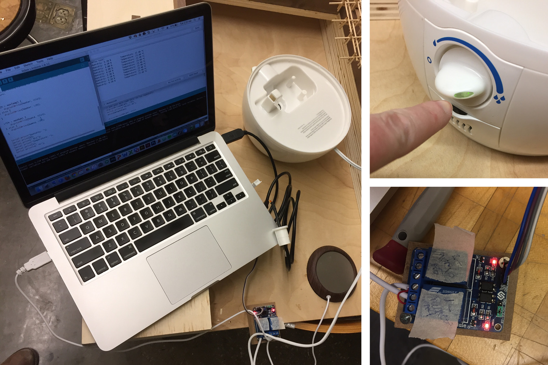
Once I got the heater (USB) and the humidifer (power) wires stuffed in there, everything went pretty smoothly after that. I even figured out the code all by myself! (with some help from the internet of course). I've learned that coding is just copying bits and pieces from other people and changing pins and inputs/outputs to match what you're doing. I'm still totally intimidated by the process, but not nearly as much as I was before. Here's the final code that I used:
		#include

		#define DHTPIN 7     // what digital pin we're connected to
		#define DHTTYPE DHT22   // DHT 22  (AM2302), AM2321
		#define humid A4
		#define heater A5

		float maxHum = 70.0;
		float maxTemp = 30.0;

		DHT dht(DHTPIN, DHTTYPE);

		void setup() {
		      pinMode(heater, OUTPUT);
		      pinMode(humid, OUTPUT);

		      digitalWrite(heater, HIGH);
		      digitalWrite(humid, HIGH);

		  Serial.begin(9600);
		  Serial.println("DHTxx test!");
		  dht.begin();
		}

		void loop() {
		  // Wait a few seconds between measurements.
		  delay(2000);

		  // Reading temperature or humidity takes about 250 milliseconds!
		  // Sensor readings may also be up to 2 seconds 'old' (its a very slow sensor)
		  float h = dht.readHumidity();
		  // Read temperature as Celsius (the default)
		  float t = dht.readTemperature(true);
		  // Read temperature as Fahrenheit (isFahrenheit = true)
		  float f = dht.readTemperature(false);

		  // Check if any reads failed and exit early (to try again).
		  if (isnan(h) || isnan(t) || isnan(f)) {
		    Serial.println("Failed to read from DHT sensor!");
		    return;
		  }


		  if(t > maxTemp) {
		      digitalWrite(heater, LOW);
		  } else {
		     digitalWrite(heater, HIGH);
		  }

		  if(h > maxHum) {
		      digitalWrite(humid, LOW);
		  } else {
		     digitalWrite(humid, HIGH);
		  }


		  Serial.print("Humidity: ");
		  Serial.print(h);
		  Serial.print(" %\t");
		  Serial.print("Temperature: ");
		  Serial.print(t);
		  Serial.println(" *F");
		}
Final Images

In the shop, no humidifier running
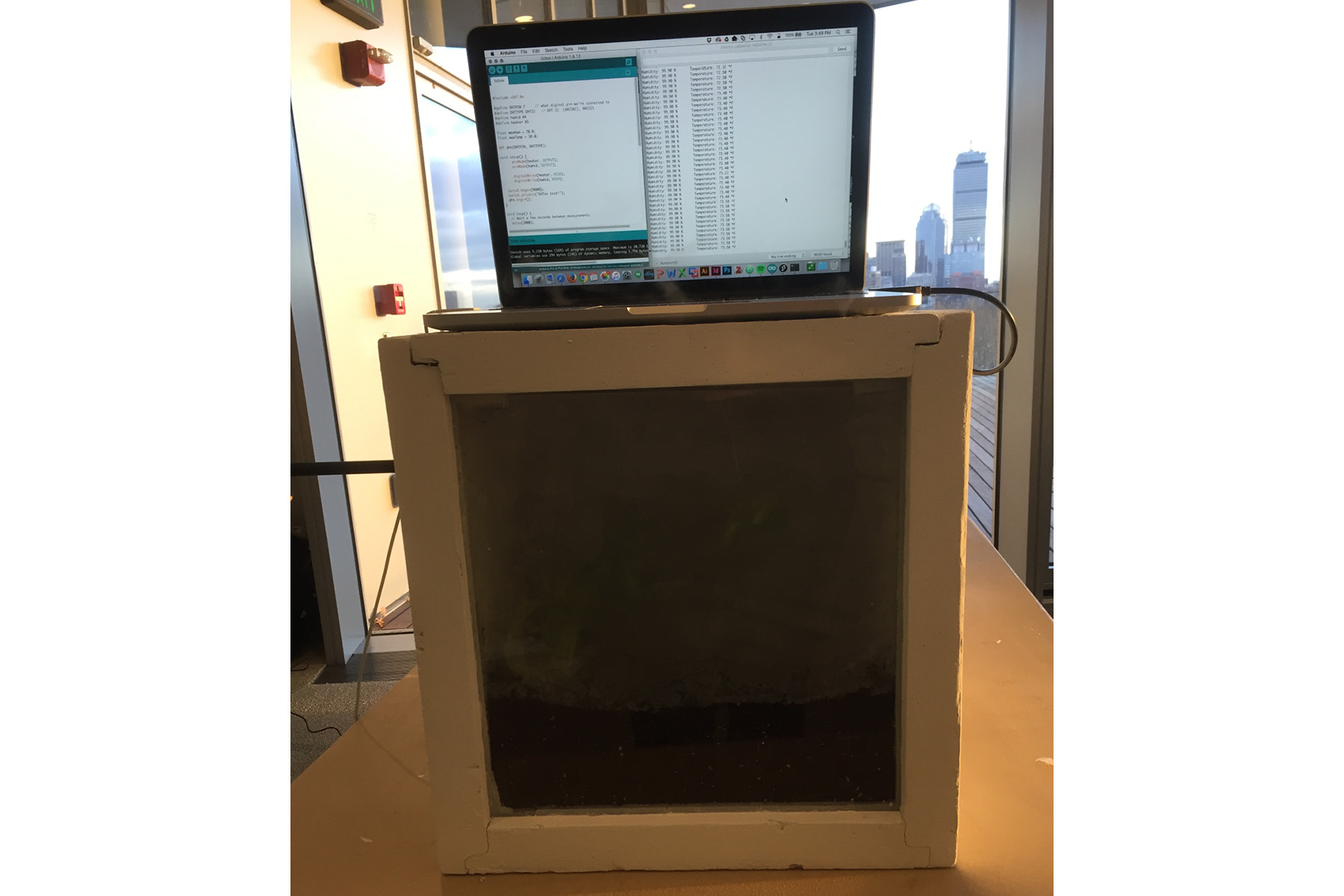
And here it is with the humidifer running... since the relay wasn't working at the final presentation, it just looked like a steamy box and you couldn't really see much of the plant. Maybe a light will be necessary.
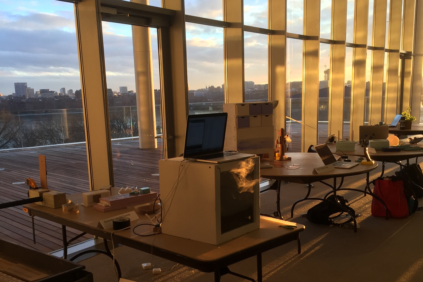
The front of the box had a large leak (I cut the plexi too short), so some of the mist was actually leaking out. It was really beautiful when the sun was shining on it. The laptop above shows the temperature and humidity readings. In the future, I'd like to integrate this into a nice interface and an LCD screen.
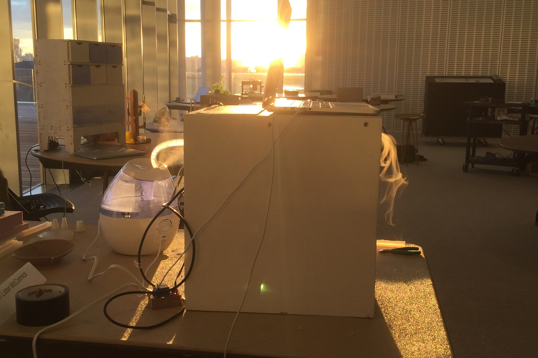
Here it is from the side with the mist coming out the front.
Temperature and Humidity readings. I literally cried with happiness when I got this working. What a cool feeling. Thank goodness for Hunmin magic. Now onto the output.
With the recommendation of my colleagues, I bought the "SunFounder 2 Channel DC 5V Relay Module with Optocoupler Low Level Trigger Expansion Board for Arduino UNO R3 MEGA 2560 1280 DSP ARM PIC AVR STM32 Raspberry Pi" to go with my fabkit board.
Using this device was somewhat intimidating since I'm actually rerouting the power supply to various devices. The first step is to cut only ONE of the two wires, stripping it, and stuffing it into the box. I never knew that power cords had two different types of wires - one is grooved/striped/ribbed and the other is smooth. The grooved wire is grounded (neutral) while the smooth wire is ungrounded (hot). The smooth (hot) wire connects to the relay, so cut that one.
I used some code that I found online to test the relay. It turns it on and off - you can tell it's working if you hear a click and the red light flashes. Very cool. Before plugging it into the power source, we made sure that the pins were active and the code was working, using a micrometer.
I should add that there is a bit of a shock risk with this thing, and Hunmin recommended that I put something over the back of the board since the pins go through. Also when you're stuffing the wires in, make sure that all the exposed wire is in there - nothing should be hanging out. This may mean that you have to cut the wire pretty short. Also, if the wires are super thin (life they were for my heater), you may have to add some Solder onto it so it stays in the pins.
Once I got the heater (USB) and the humidifer (power) wires stuffed in there, everything went pretty smoothly after that. I even figured out the code all by myself! (with some help from the internet of course). I've learned that coding is just copying bits and pieces from other people and changing pins and inputs/outputs to match what you're doing. I'm still totally intimidated by the process, but not nearly as much as I was before. Here's the final code that I used:
#include
#define DHTPIN 7 // what digital pin we're connected to
#define DHTTYPE DHT22 // DHT 22 (AM2302), AM2321
#define humid A4
#define heater A5
float maxHum = 70.0;
float maxTemp = 30.0;
DHT dht(DHTPIN, DHTTYPE);
void setup() {
pinMode(heater, OUTPUT);
pinMode(humid, OUTPUT);
digitalWrite(heater, HIGH);
digitalWrite(humid, HIGH);
Serial.begin(9600);
Serial.println("DHTxx test!");
dht.begin();
}
void loop() {
// Wait a few seconds between measurements.
delay(2000);
// Reading temperature or humidity takes about 250 milliseconds!
// Sensor readings may also be up to 2 seconds 'old' (its a very slow sensor)
float h = dht.readHumidity();
// Read temperature as Celsius (the default)
float t = dht.readTemperature(true);
// Read temperature as Fahrenheit (isFahrenheit = true)
float f = dht.readTemperature(false);
// Check if any reads failed and exit early (to try again).
if (isnan(h) || isnan(t) || isnan(f)) {
Serial.println("Failed to read from DHT sensor!");
return;
}
if(t > maxTemp) {
digitalWrite(heater, LOW);
} else {
digitalWrite(heater, HIGH);
}
if(h > maxHum) {
digitalWrite(humid, LOW);
} else {
digitalWrite(humid, HIGH);
}
Serial.print("Humidity: ");
Serial.print(h);
Serial.print(" %\t");
Serial.print("Temperature: ");
Serial.print(t);
Serial.println(" *F");
}
Final Images
In the shop, no humidifier running
And here it is with the humidifer running... since the relay wasn't working at the final presentation, it just looked like a steamy box and you couldn't really see much of the plant. Maybe a light will be necessary.
The front of the box had a large leak (I cut the plexi too short), so some of the mist was actually leaking out. It was really beautiful when the sun was shining on it. The laptop above shows the temperature and humidity readings. In the future, I'd like to integrate this into a nice interface and an LCD screen.